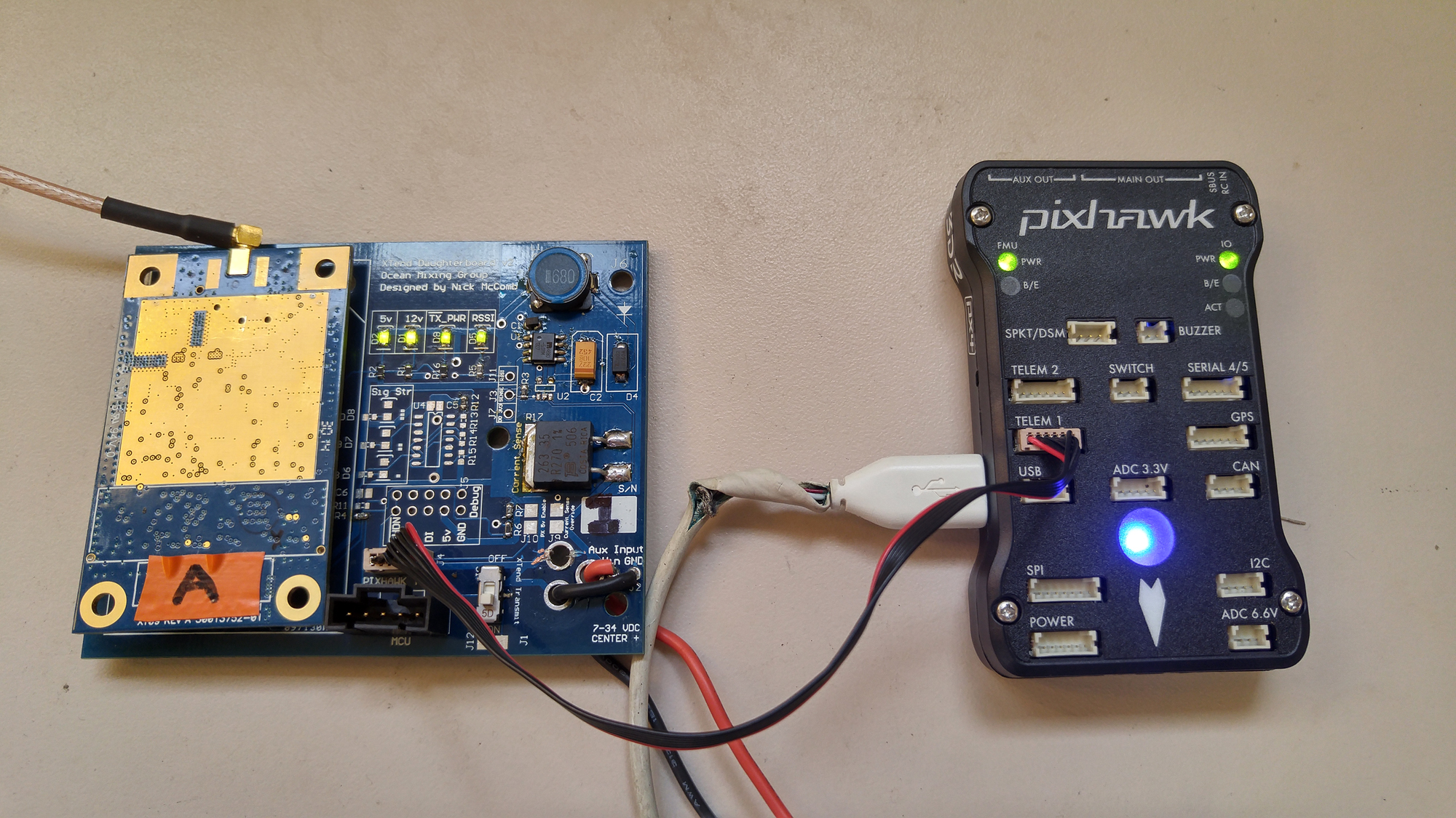
Board Summary
This was originally designed for the ROSS project.
This board was designed to be a “Daughterboard” for the Digi XTend Wireless module, as it requires extra hardware to be plug and play with a 3v3 serial device. The features are summarized below:
- Breaks out the XTend’s 2mm (not standard .1″ spacing) pins and routes signal and power appropriately.
- Provides 2A @ 5v from any source from 7v – 16v (designed for a 12v SLA pack)
- Preforms Logic Level Shifting of the 5v Serial signal coming out of the XTend to be received by the Pixhawk (or any other 3v3 device)
- Provides current sensing and easy interface to a 5v serial device (uC, RasPi, etc) via a Molex Connector
- Provides a switch to turn of XTend transmission for debugging purposes
Version 4 of the board can be used as a ground station interface (as it includes a USB-to-serial converter).
Version 3 of the board (including Version 3 improved) is used in the EBOX, as it doesn’t need the extra circuitry.
Board Pinout
DF13
The DF13 (Pixhawk) connector on the board is designed to work with the Pixhawk “TELEM” ports. It’s pinout is as follows:

XTend DB DF13 (Pixhawk Connector) Pinout
Pin 1 is marked “+” and is on the “right” (farthest from the XTend).
MCU
The port labeled “MCU” or “MCU Conn” is designed to interface with a 5v Microcontroller. The connector on the board is DigiKey part no WM4803-ND, and It’s pinout is as follows:

XTend DB MCU Molex Connector Pinout
Pin 1 is marked, and is on the “left” (closest to the XTend).
Project Downloads
XTendDaughterboard v4 Schematic
XTendDaughterboard v3 Schematic (pdf)
XTend Daughterboard v3 Design Files (Altium Designer)
Old Versions
XTend Daughterboard v2 Design Files
XTendDaughterboard v2 Schematic
XTend Daughterboard v1 Design Files (source files are in a zip)


