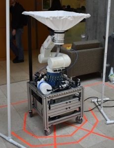
ECE 322 Variable Power Supply
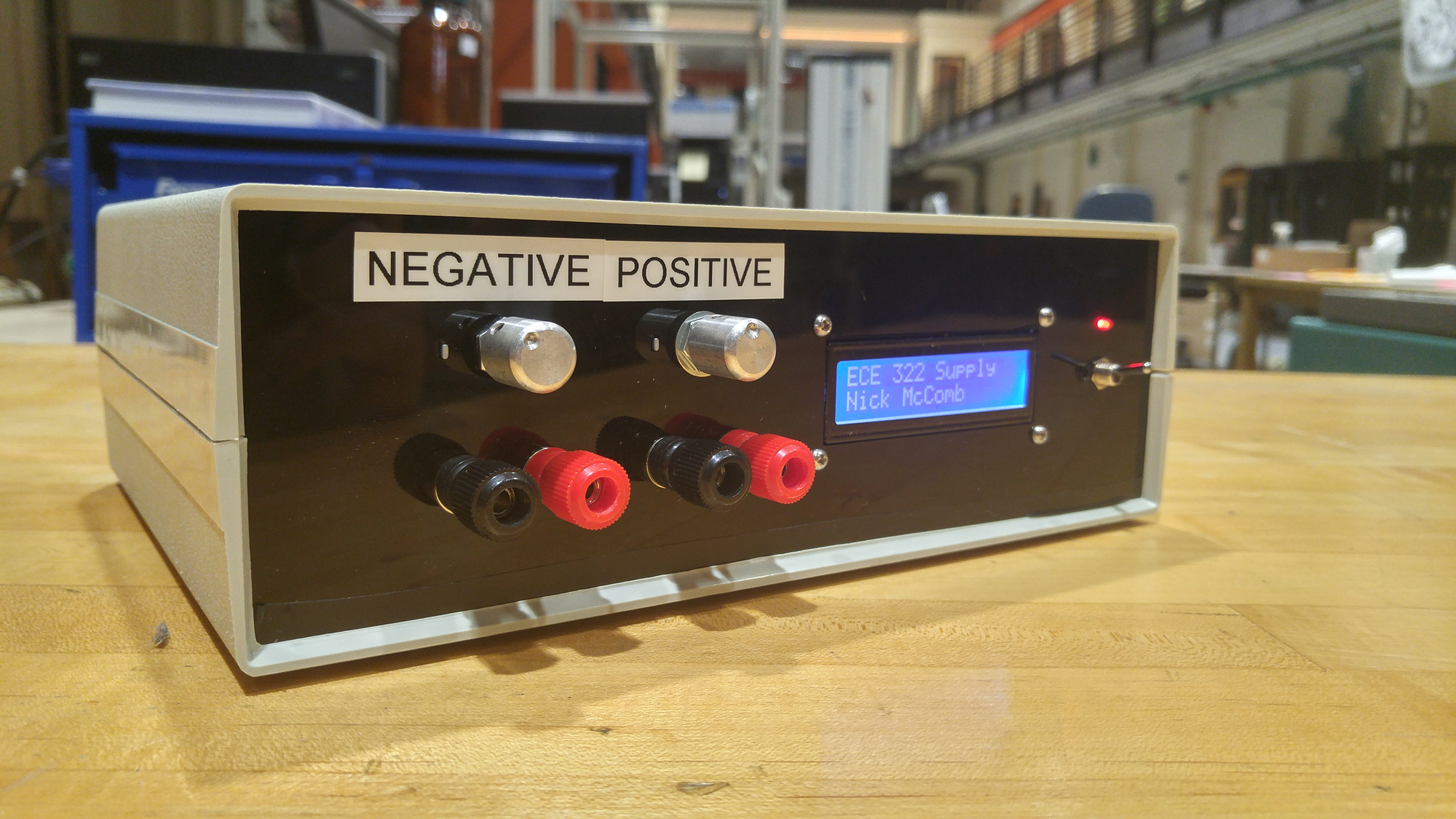
Picture of the final product. The screen is displaying a title in “initialization” mode.
Project Summary
This project as a variable voltage regulator that I made for an ECE class (ECE 322: Electronics I). The project was implemented over 10 weeks during the lab for the class. The project served as a hands-on application for topics that we studied in lecture. These topics includes Diodes, MOSFETs, BJTs, filters, OpAmps, and more. The project was a great way to apply skills learned in class to something that can be useful in your every-day life! Even on your bench in your lab (although I will always likely defer to a professionally made and produced power supply, I don’t want to rely on anything that has ‘protoboard’ in it when working on my projects).
Project Specification Document
As part of the project, I created a “Project Spec” document which details all of the circuits that I used in my design, and includes descriptions of their operation. I’ll omit discussion of those circuits in leu of allowing the reader to read the Project Spec document. I will discuss some of the extra credit that I implemented just for fun (it was unclear as to whether I actually got any extra points for it).
The project’s high level specifications can be found below:
- 2 to 12v adjustable Voltage output rail
- -2 to -12v adjustable Voltage output rail
- All outputs current limited to ~1A (+/- 10%)
- Temperature activated cooling circuit
- Voltage output display
Extra Credit
Voltage Output Screen
For this assignment, I decided to go above and beyond, and I implemented a display for my power supply. For this project I used an Arduino Pro mini as my Microcontroller, primarily to test a new programmer that I had just received in the mail (DF Robot XSP). The block diagram for the display can be seen below.
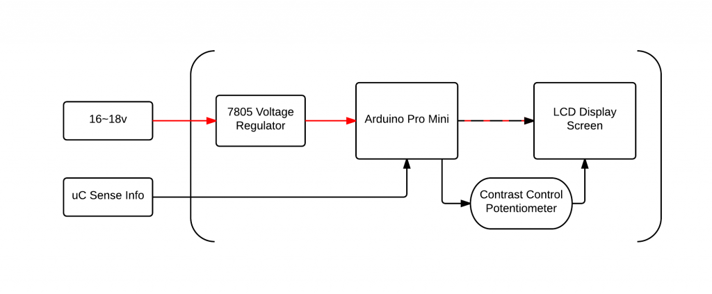
ECE 322 Diagrams – Display Block Diagram
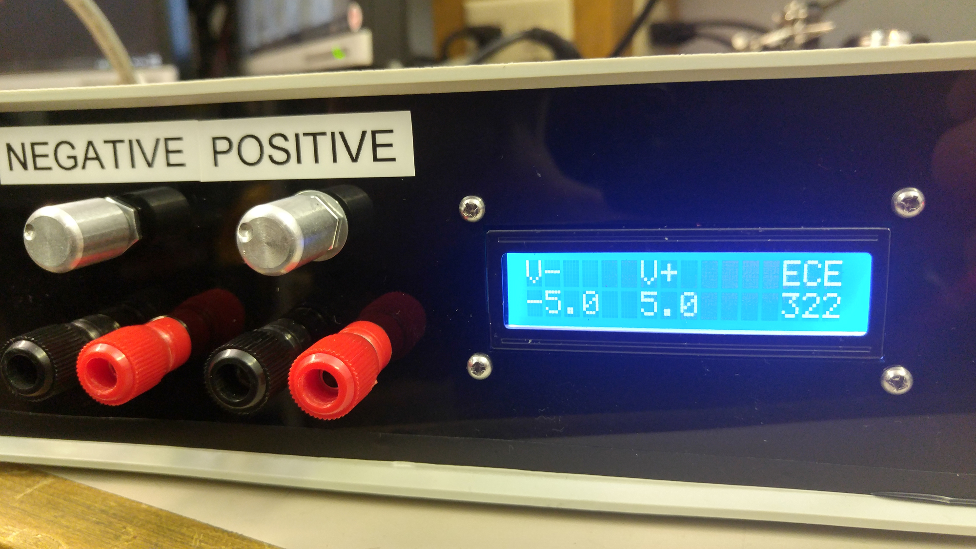
Display measuring voltage from the outputs.
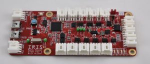
PCB
I also implemented a PCB for my voltage regulator circuit. It can be seen pictured below, for more info, please go to it’s page in my PCB documentation, here.
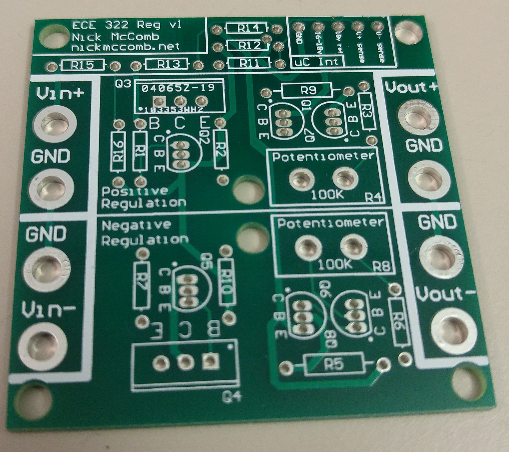
A Voltage Regulator PCB, the “core” of the project.
Submodule Links
Voltage Regulator PCB Documentation
Project Code Documentation (Github)
Description Video
I recorded a short video describing this power supply for the EECS Mastery Challenge (Analog Circuits Level 3).