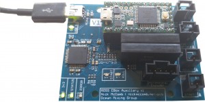
Version 1 of the Auxillary Board during testing.
Board Summary
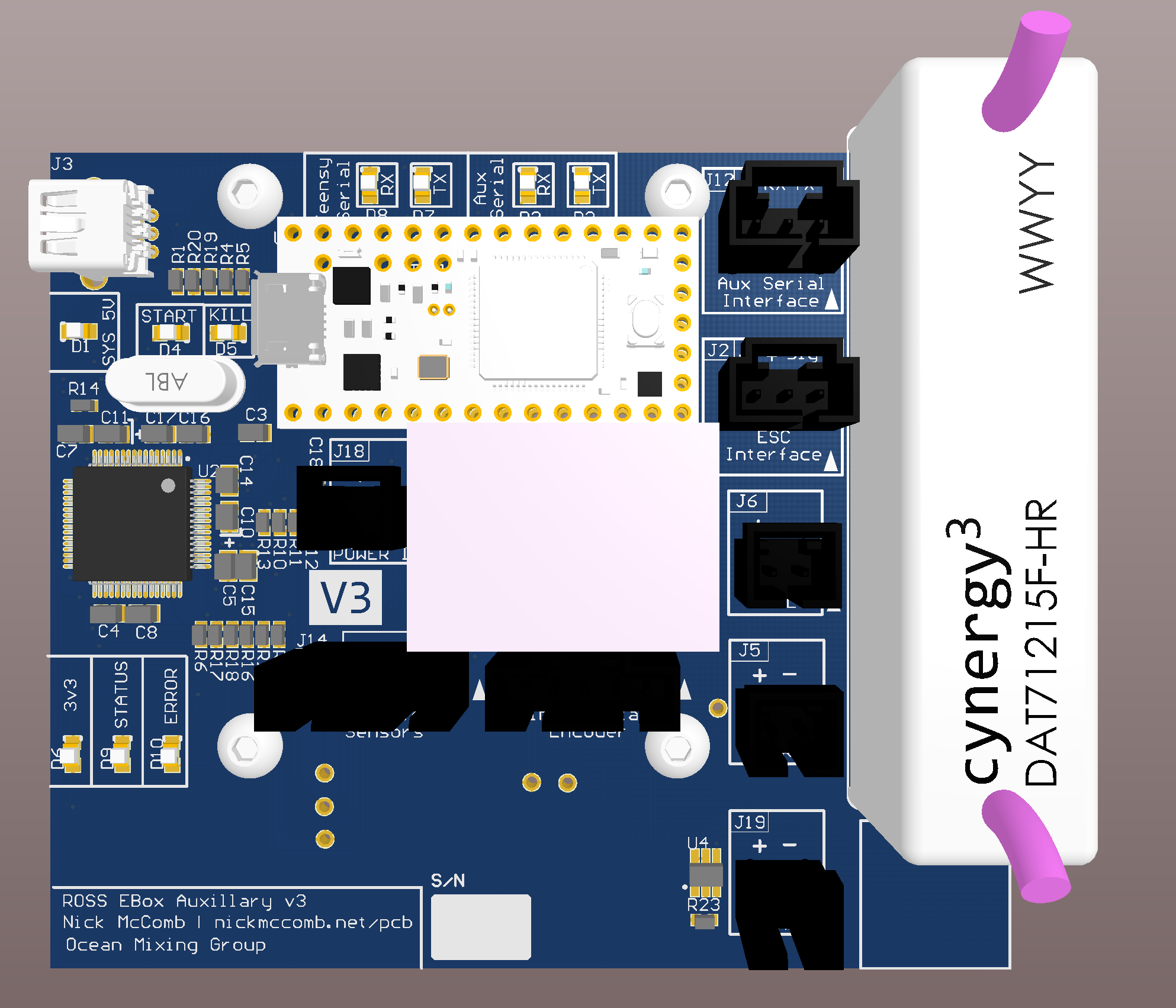
Version 3 of the Auxillary board.
The Auxillary Board was created as a “catch all” to support kayak operations. It performs functions that were otherwise left out of other systems designed into the Electronics Box on the kayak. The board performs 3 primary operations: kayak winch control (optional), “Remote Start” and “Remote Kill” functionality, is a “USB to Serial” bridge for the Flight Management Unit (FMU) (or any other single device that requires it). It was originally an assimilation of projects by Corwin Perren (www.caperren.com) and Robert Shannon. It’s Teensy enabled!
Formal Documentation (currently out of date)
Features
The most recent version of this PCB has the following features:
- Teensy 3.2 Microcontroller
- FTDI FT2232 Dual USB to UART Bridge
- Incremental Hall Effect Input
- ESC Output (PWM Signal)
- Flex Sensor (variable resistor) Input
- Aux Serial Device Input
- Engine Start Relay
- Engine Kill Relay
- 1-Wire® Temperature Sensor Support
- SD Card for Debugging Datalogging
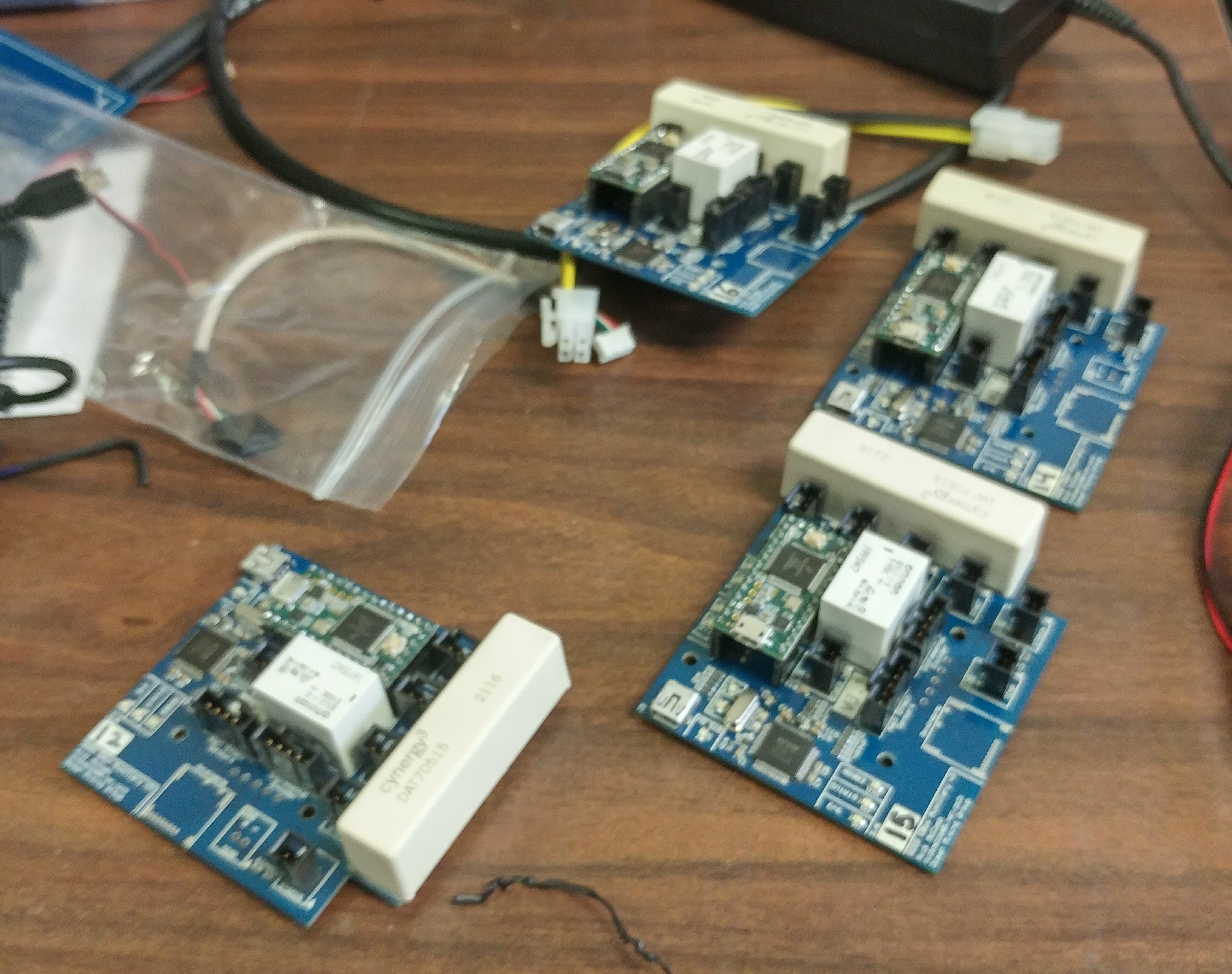
4 assembled Version 3.1 Aux Boards.
Board Pinout (currently out of date)
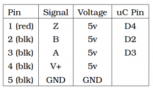
Incremental Encoder
ESC Output
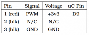
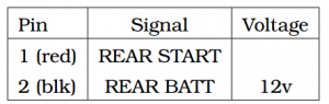
START signal
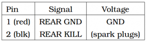
KILL signal
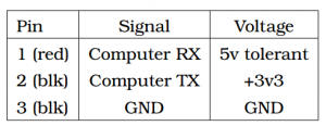
Auxillary TX/RX
Downloads
ROSSEBoxAuxillary Schematic v3.1
ROSSEBoxAuxillary Schematic v3
ROSSEBoxAuxillary Schematic v2.1
ROSSEBoxAuxillary Schematic v2
ROSSEBoxAuxillary Schematic v1
ROSSEBoxAuxillary 3D Model (requires Adobe Reader)
FTDI RS2232 EBox Auxillary Template.xml
Media
Aux Board starting ROSS’s engine during lab testing.